

Hi all, In this post, I will cover how to add USB type C to ESP32 development board, or any other PCB project that you want to create. But, why? Why I’m creating a custom ESP32 Dev board when there are a lot of thirty parties boards on the market? Why USB type C?
The point isn’t to create jet another ESP32 Dev board but to have a platform on which I can build any other project that requires ESP32 and a custom PCB. Because of that, I’m just adding only the necessary components and nothing extra. The USB type C is for convenience. In 2022 every Phone or any electronic device is switching to type C, so we can use only one charger for everything.
And now when we covered that we can start, and right away let’s split this post into two main sections
- Add schematic, Footprint, 3D model view, and availability from JLCPCB
- Direct connection from USB to ESP32-S2
- Powering ESP32
Also if you are interested in this topic check out my other post on ESP32 https://blnlabs.com/how-to-add-esp32-to-kicad/
There is as well YouTube video from Altium Academy on how to add USB type C connector for our projects.
Also, this post will work only with the ESP32-S2 variant because S2 has embedded USB-OTG, and without this block, we need to use an external USB to UART chip in order to communicate with our ESP32.
Add schematic, Footprint, 3D model view and availability from JLCPCB
There are a lot of options for what to use and which variant, so you can not make a large mistake, but for this project and post I took the next component. In the YouTube video below you have the full process for adding a USB type C connector component.
For Schematic Symbol we are using USB_C_Receptacle_USB2.0 from the default KiCad library
Also for Footprint, we are selecting from drop-down menu from default library Connector_USB:USB_C_Receptacle_HRO_TYPE-C-31-M-12
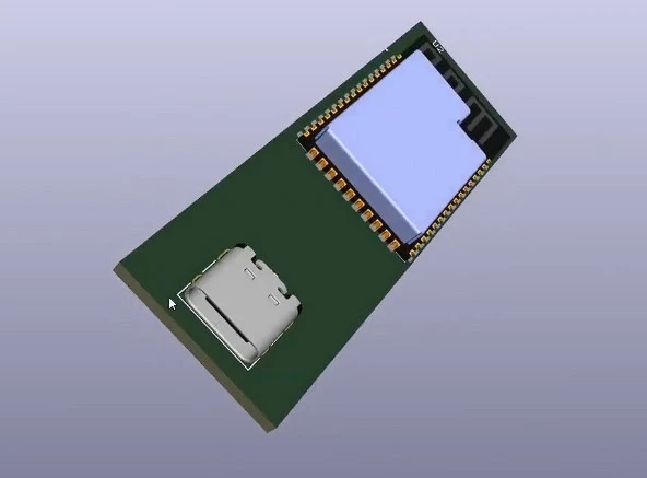
3D Model View wasn’t built so we needed to find the model online and can be found at the next link https://grabcad.com/library/type-c-31-m-12-1
And we can use the component for JLCPCB from the next link https://jlcpcb.com/partdetail/Korean_HropartsElec-TYPE_C_31_M12/C165948
Direct connection from USB to ESP32-S2
For this custom board with ESP32, I want to use native USB and not use some USB to UART chip. So, we need the connection between the USB contractor and our ESP32-S2-WROOM. There is a good article on this topic at https://www.pcbway.com/blog/PCB_Design_Tutorial/How_to_add_USB_C_to_your_projects.html
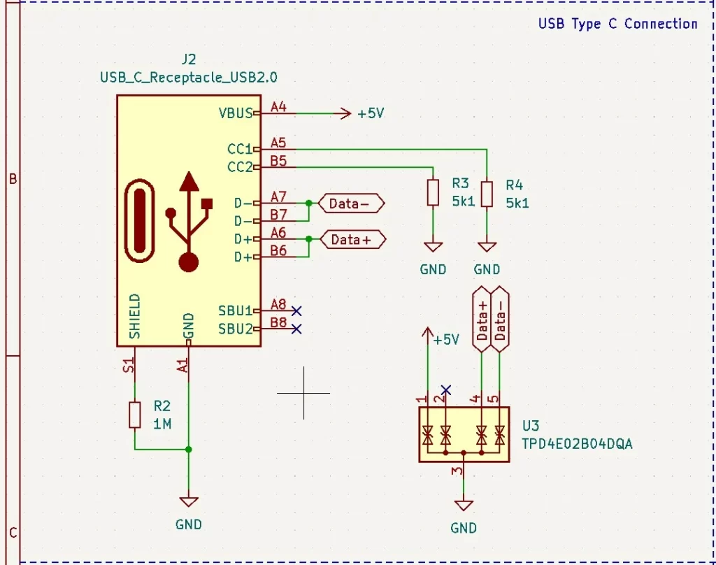
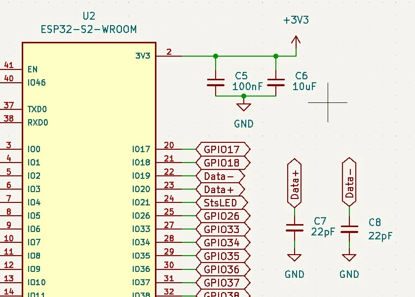
So in order to add USB type C to ESP32, we need to directly connect data lines from the USB connector to our ESP32, and we need to add a couple of resistors and just some voltage protection. Besides this, we simply need to add pair of capacitors for data lines.
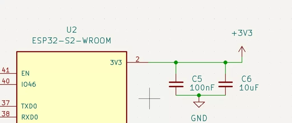
Powering ESP32
From the USB type C connector, we are getting +5V on the VBUS pin. This is too large a voltage to power our ESP32 directly, so we need to introduce a linear voltage regulator in between to drop the voltage from +5V to +3.3V. I also created a YouTube video on how to use AMS1117 voltage regulator for ESP32.
But inside KiCad voltage regulator should look something like in the image below.
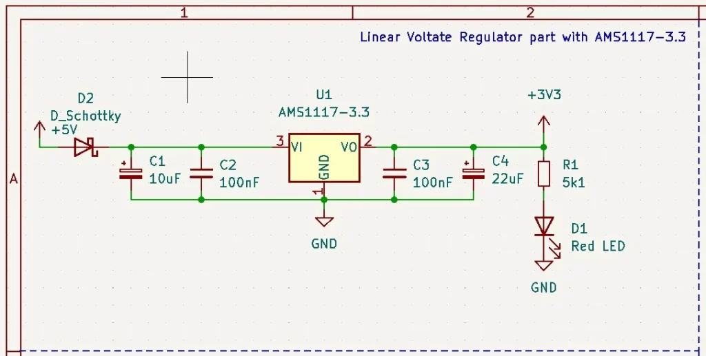
In the image above we have only the addition of the Schottky diode that is used as a reverse polarity protection diode. The last thing we need to add is a couple of capacitors close to the 3V3 pin of ESP32 in order to have a steady power voltage.
And at the end, we can see all connections in the image below. We have our Data+ and Data- going directly to IO19 and IO20 pins.
Final words
And that is it. We needed to do three things in order to add USB type C to the ESP32 Development board or any project. Add a connector, add a direct connection to ESP32 and add a linear voltage regulator in order to power ESP32 correctly. Of course, only this is not enough for the full functional development board, and in order to have a custom development board we need to add a couple of things, but that will be covered in the next video and/or post. Comment down below and see you in the next one.
What are the advantages of using native USB vs using an USB to UART chip?