

Hi all. I will take a reasonable guess that you know what ChatGPT is and that you are probably being bombarded with content on how to make money with ChatGPT without moving a finger, or how to fix your life problems by engineering better prompts for this AI wonder. And ChatGPT is amazing, but I think only for learning new stuff faster and automatization. So, in this post, I will try to learn with ChatGPT about Round LCD Displays that I want to integrate into my next project.
Also, check out my other projects:
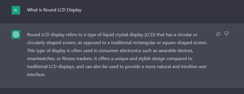
What is Round LCD Display?
As we see pretty accurate descriptions. But I would like to do my initial testing with GC9A01 1.3 Inch Round 240X240 LCD Display Module. Let us see if can ChatGPT give us this option.
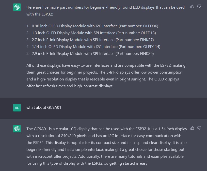
ChatGPT didn’t manage to suggest the GC9A01 but I think that is completely ok. This is just the round LCD that I have on hand, so I’m pushing for that one 🙂 But when we asked about GC9A01, ChatCPT gave us the correct answer, and we can learn some interesting stuff.
- Resolution: 240×240
- Display size: 1.54 inch
- Communication: I2C (mine GC9A01 board is actually using SPI, but more on that later)
But can we get more info on this round LCD display?
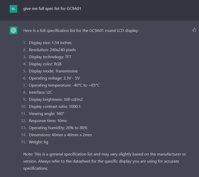
And maybe here is the first problem. Operating voltage: 3.3V – 5V. Mine device is suitable for 3.3V only, but because of that we also have a disclaimer from chatGPT that we need to check inside GC9A01 datasheet also.
Ok, so far so good but how to start with GC9A01? Let us see the answer.
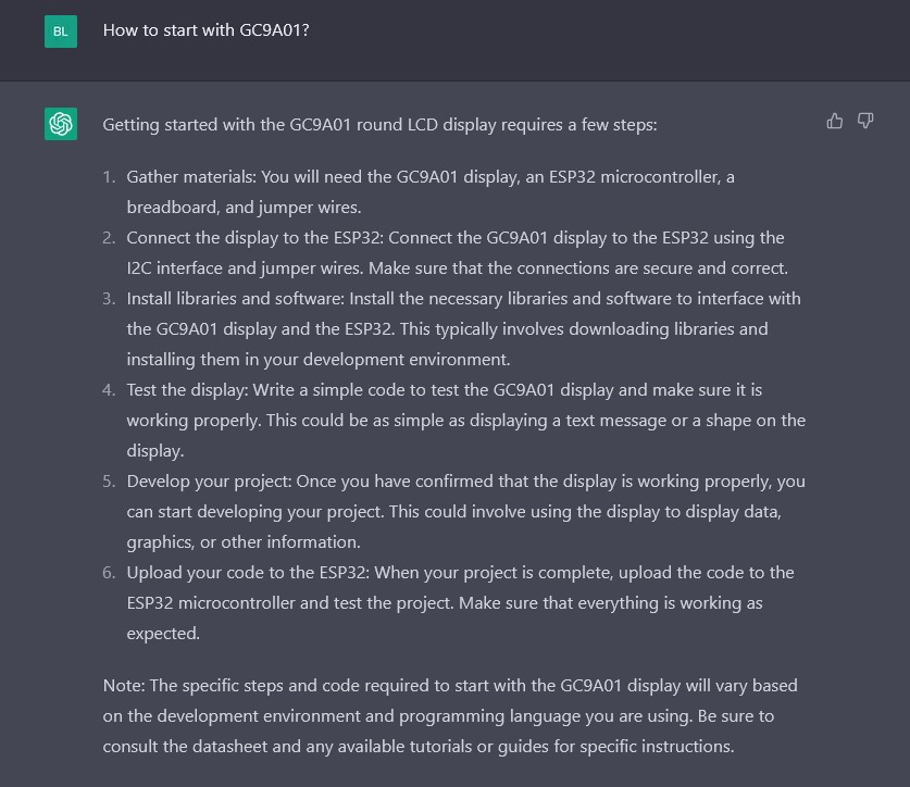
Gather materials: You will need the GC9A01 display, an ESP32 microcontroller, a breadboard, and jumper wires.
Done.
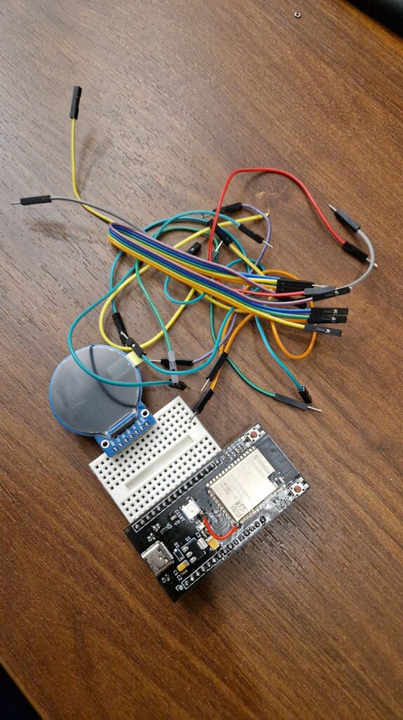
For this example, I’m using:
- My custom ESP32-S2 development board that is made from scratch (check out my other content on that topic) alternative is SparkFun Thing Plus – ESP32-S2 WROOM
- GC9A01 LCD round display
- Small Breadboard with Breadboard Jumper Wires
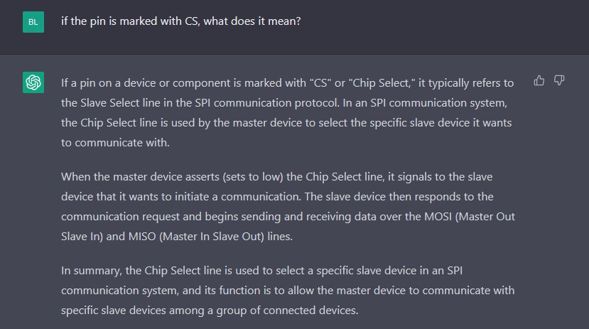
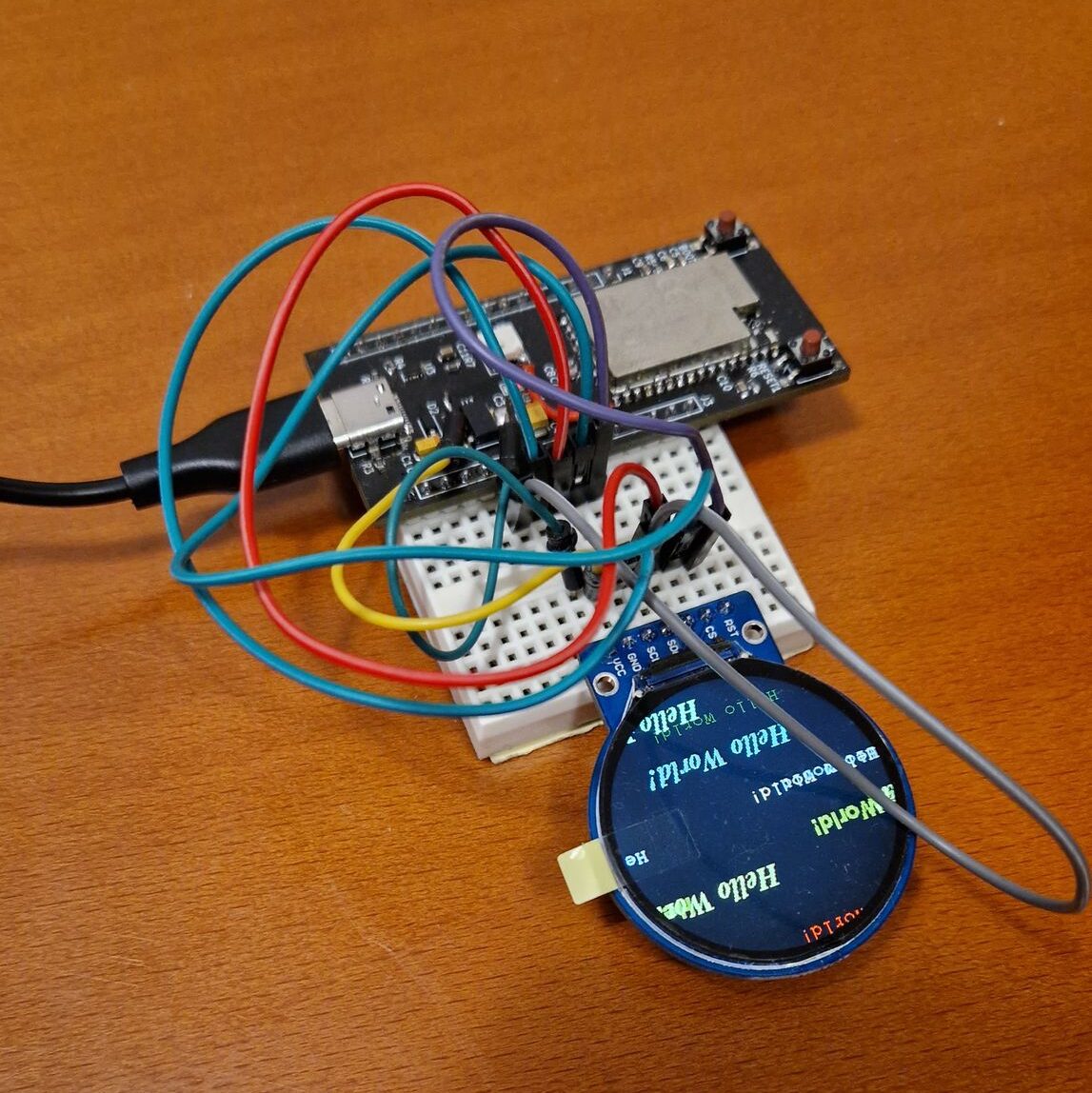
Nice, but my GC9A01 doesn’t have an LED pin and it has a CS pin or chip select and now we need to do some manual engineering.
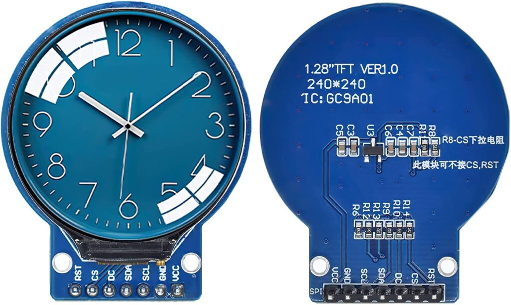
In the image above I’m showing my Round LCD display, and our problem. When I asked ChatGTP about signals SCL and SDA, I got the correct answer.
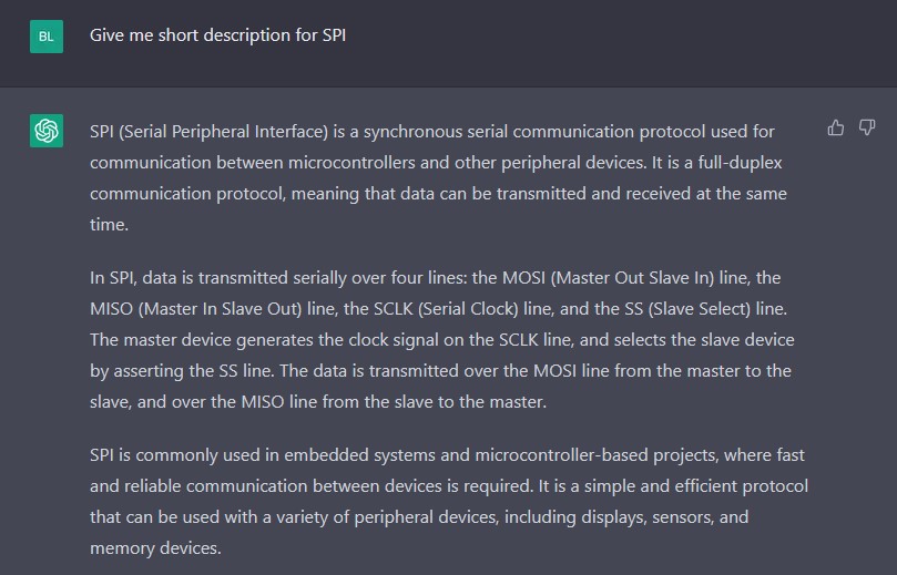
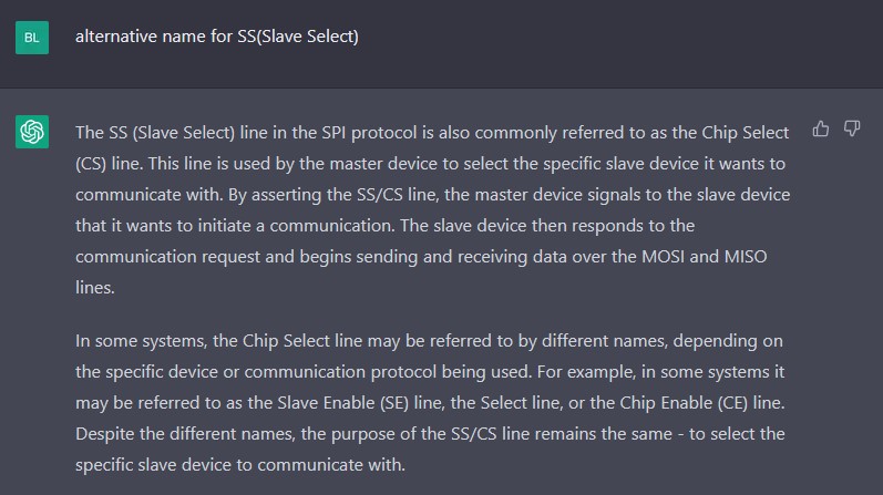
Those two are pins dedicated to I2C communication, but why is there then CS pin (chip select pin)? And here you need to relay a bit on your knowledge. I know that the CS pin is used not for I2C communication but for SPI. So I would guess that maybe descriptions on SDA and SCL pins are wrong and that we have SPI instead I2C communication. But can ChatGPT come to this conclusion?
So, let us ask ChatGPT about SPI communication.
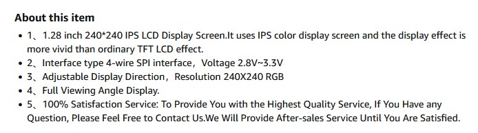
And then I confirmed with date from the Amazon site.
So, I determined that we actually have SPI communication with Chip Select, SCL as the clock line SCLK, and SDA as the data line or MOSI in SPI terminology.
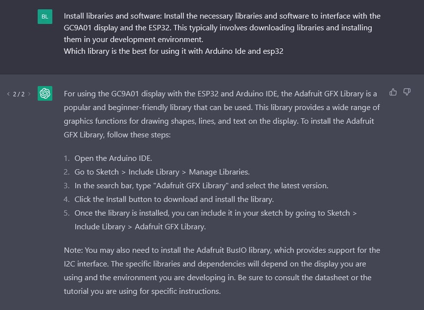
And only at this point I could connect the LCD display to the ESP32-S2 development board correctly and continue the software pare, and install the libraries for Arduino IDE in order to control the round LCD display with ChatGPT help. Also, until now we got some wrong replay from ChatGPT, but then we needed to ask some additional questions and to get maybe even more knowledge by Learning with ChatGPT.
Software part
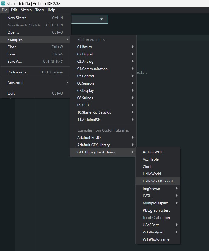
We have our hardware linked and connected now we need software. I will use it for this post, Arduino IDE (even though I like a Platform IO a bit more, but that can maybe be a bit too complex for chatGPT so let us make it simple).
I just copied a paragraph and asked it to give me more details.
And then some more options.
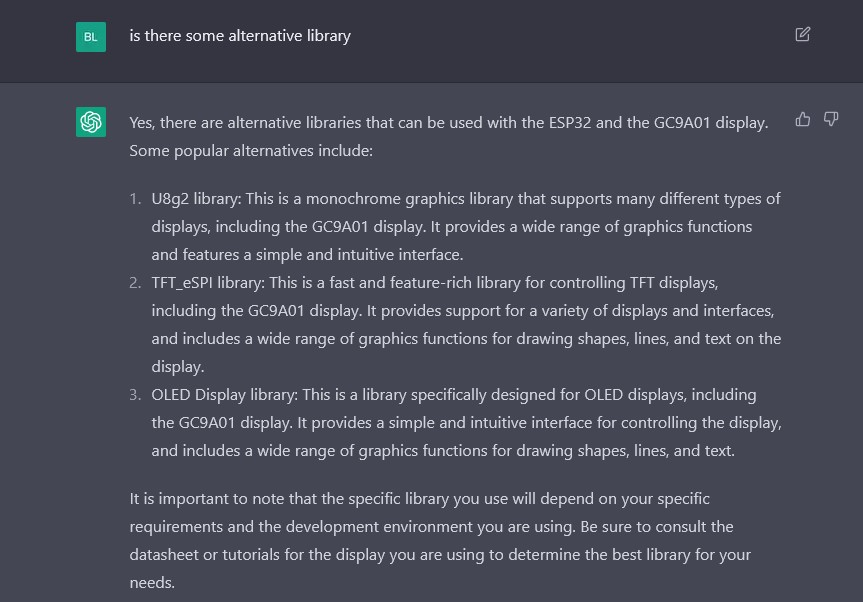
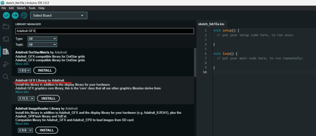
Why more options? I’m familiar with the Arduino GFX library which was some good examples out of the box and I wanted to try it. But It seems that ChatGTP will only give me the Adafruit GFX library. So let us install that one as well.
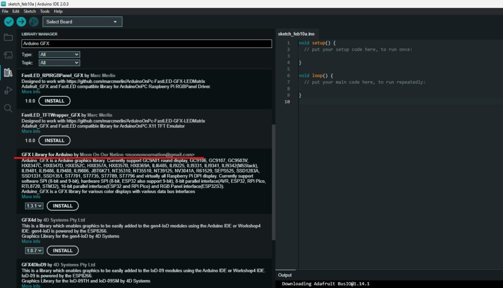
And then Arduino GFX as well.
Now, let’s try an example that will display Hello World on our display.
We simply need to adopt the config part a biting order to play nicely with our custom board.
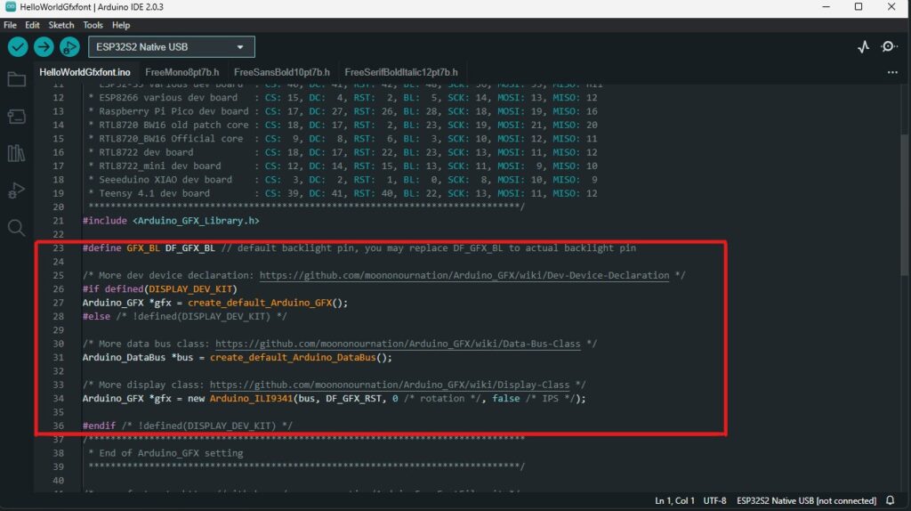
We simply need to use the next lines
#define GFX_BL DF_GFX_BL // default backlight pin, you may replace DF_GFX_BL to actual backlight pin

/* More data bus class: https://github.com/moononournation/Arduino_GFX/wiki/Data-Bus-Class */
Arduino_DataBus *bus = new Arduino_SWSPI(37 /*DC*/, 38 /*CS*/, 36 /*SCK*/, 35 /*MOSI*/, GFX_NOT_DEFINED /*MISO */);

/* More display class: https://github.com/moononournation/Arduino_GFX/wiki/Display-Class */
Arduino_GFX *gfx = new Arduino_GC9A01(  bus, 39 /*RST*/, 0 /*rotation*/, true /*IPS */);
And as you can see I’m using GPIO37 for the DC pin, GPIO38 for CS, GPIO36 for the clock, and GPIO35 for MOSI(data). In the second command, we are defining a connection from GPIO39 to the RST pin and that is it.
Final words
And that is pretty much it for the init step in this project. With ChatGPT this step can be shortened by a lot and you can learn a lot of stuff in the progress. I’m hoping that you will learn something from ChatGPT and that you can make some great things with this amazing tool.