

Hi all. Welcome to the blog post about how I integrated ESP32 into my Car over the OBD2 port. In this post, I will cover the part on how to Power ESP32 from the OBD port, or actually how to power ESP32-S3 from 12V. There are multiple ways how this can be done, but I will give my way and reasoning behind each choice. So, let us begin.
Connector/Port
As we probably know if we want to get any information from the car we need to connect to the OBD port. It is usually located below the steering wheel and it looks something like this.
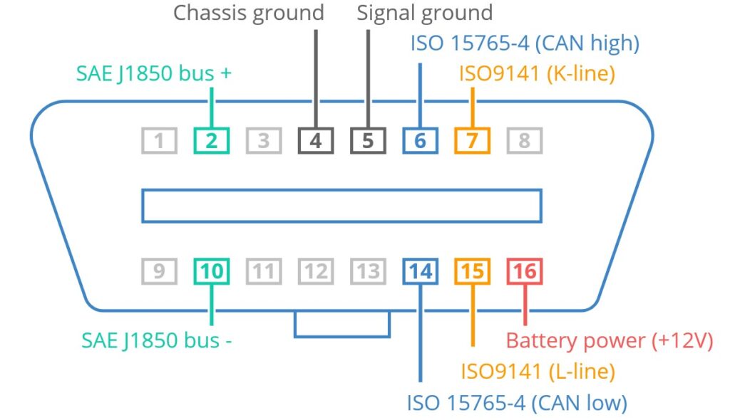
For now, we need to focus only on power, or on +12V and Ground pins. I wanted to, as the first step only correctly power ESP32 from the OBD port, and we need pins 16 and 4 or 5.
Check out my other post on a the CAN bas at https://blnlabs.com/can-dbc-compare-tool/
Voltage Conversion
Next, I need to somehow convert 12V to 3.3V which is required by ESP32. Also, I needed to take into account do we need some additional voltage level, for example, 5V. This is a widely used voltage level and there are a lot of implementations that are dropping down from 12V to 5V and only then from 5V to 3.3V. But for this project, I would like to use only a 3.3V voltage level so I’m sipping 12V to 5V dropdown, and from now on every component that I will be using needs to be a 3.3V complement.
Voltage Regulator vs Converter
There are a couple of ways how to convert one voltage level to another voltage regulator and Converter. There is much information online on comparisons between these two approaches and I will link only one YouTube video (https://www.youtube.com/watch?v=giGRrODKJSE). I chose a converter, a Buck converter, that will drop down from 12V to 3.3V. I think that a linear voltage regulator, in this case, would be so inefficient when dropping down from 12V to 3.3V (this is a good option when dropping down from 5V to 3.3V), so a converter it is.
I searched online for a couple of solutions that are already used for a similar use case and I found two components that would work for me.
- LMR14006 SIMPLE SWITCHER® 40 V 600 mA Buck Regulator
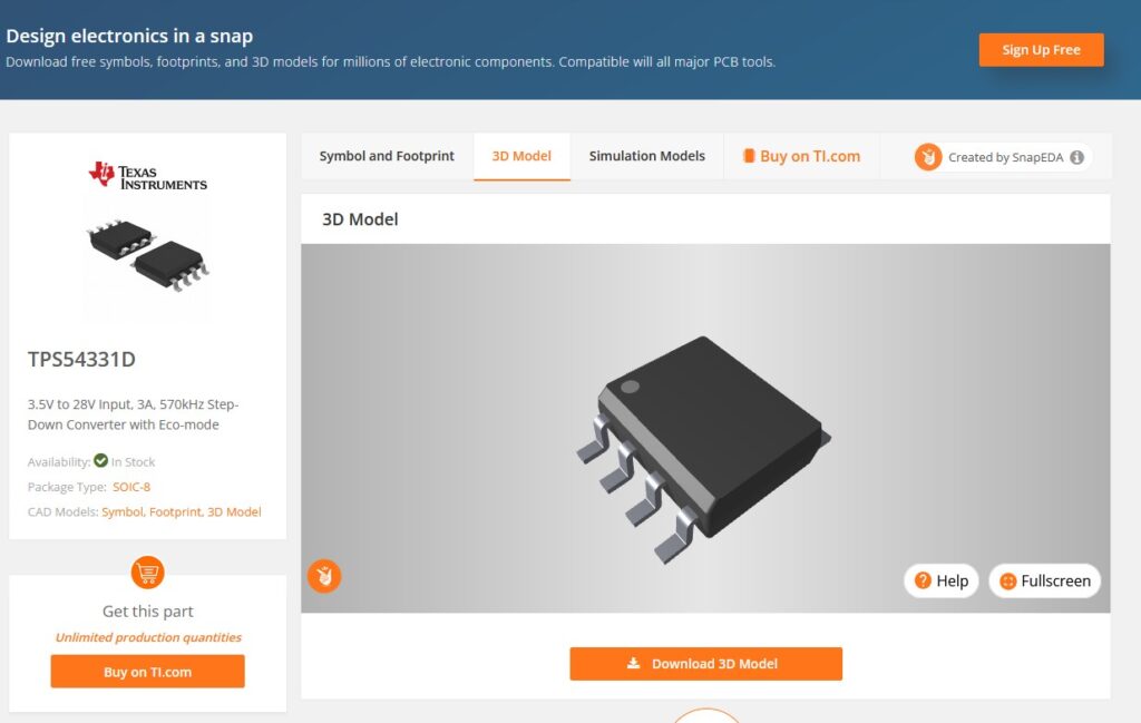
- TPS54331 3-A, 28-V Input, Step Down DC-DC Converter With Eco-mode
Both should be a fine choice, but for this post, I will use TPS54331. The most important document is the datasheet at the next link https://www.ti.com/lit/ds/symlink/tps54331.pdf?ts=1678446821707.
Here we can see all the specifications and further we can see the topical application, which we can reuse for our implementation.
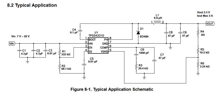
The documentation is pretty clear, and if you want to go into the details you can. All formulas and decisions behind certain values are shown in this pdf, but I you want a 12V to 3.3V step-down converter, you can just use the given value in the image above.
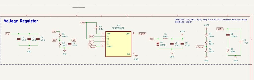
After a short time, we moved this typical Application schematic to your desired PCB editor (in my case that is KiCad) and, for me. it looks something like this.
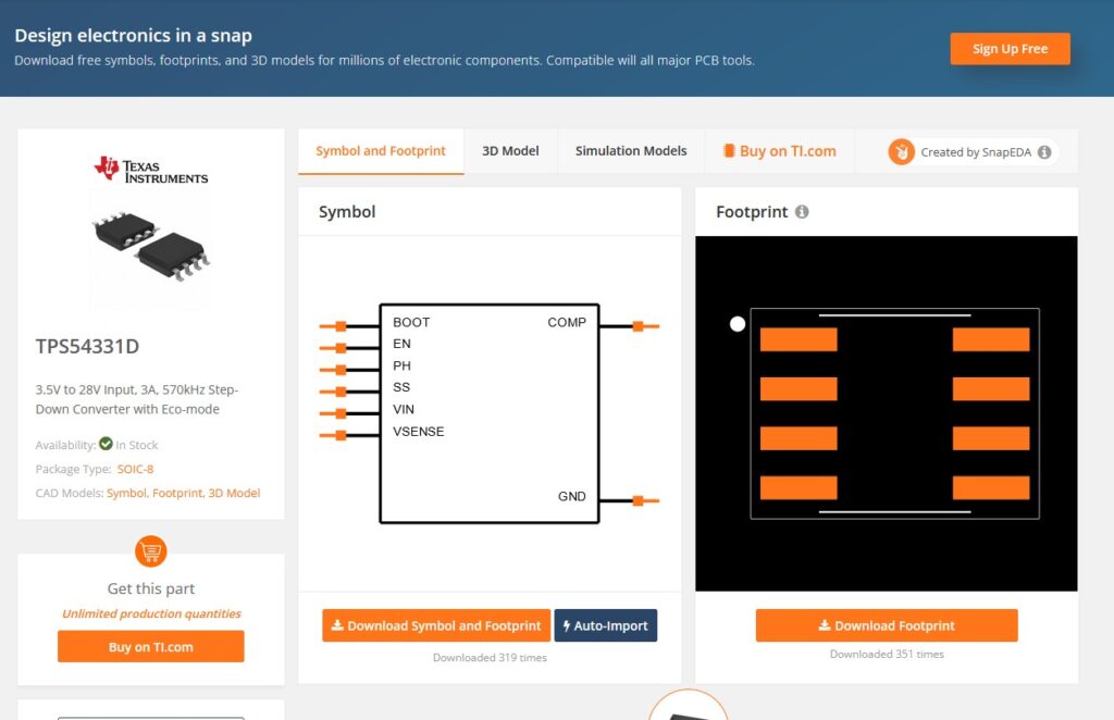
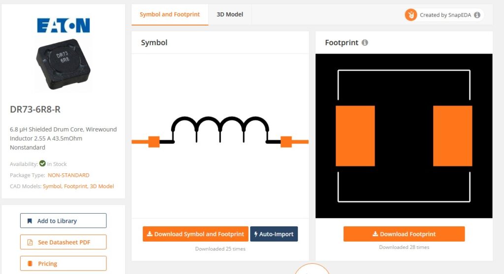
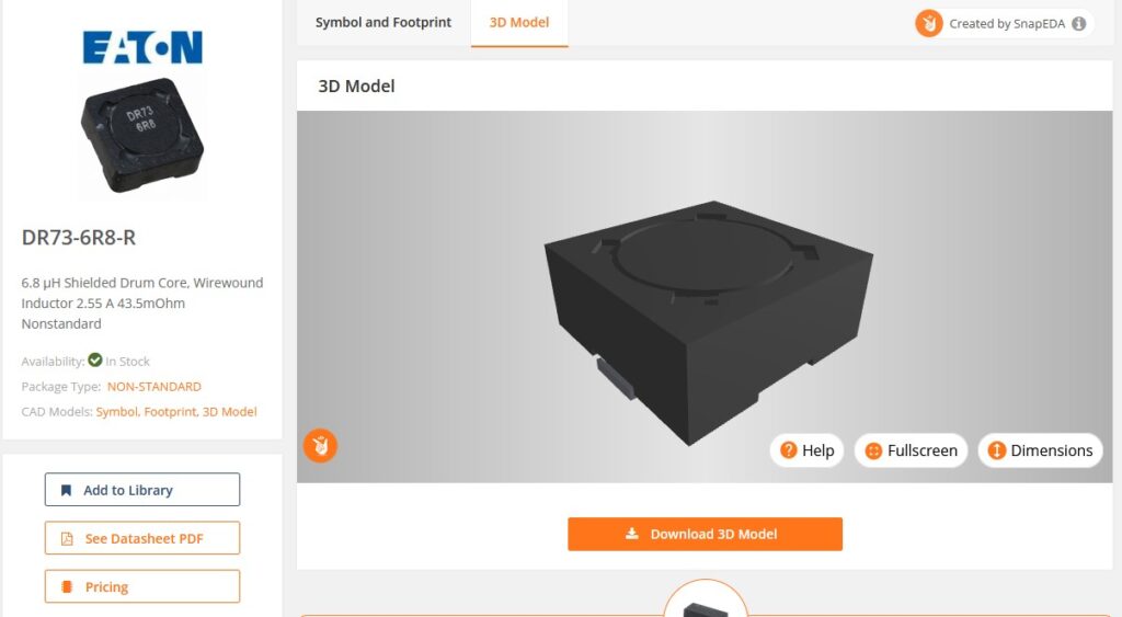
I didn’t have a schematic symbol only for TPS54331, but with a simple search on SnapEDA, I found a schematic, footprint, and 3D model for this component.
Then, because we have a larger inductor 6.8uH we need a specific footprint and 3D model, and I wanted to use a shielded inductor, so I picked SLH0704S6R8MTT and found a footprint and 3D model that will work with this.
After this, we should have a working 12V to 3.3V step-down converter made in order to power ESP32 from the OBD2 port in your car. But …
Protection
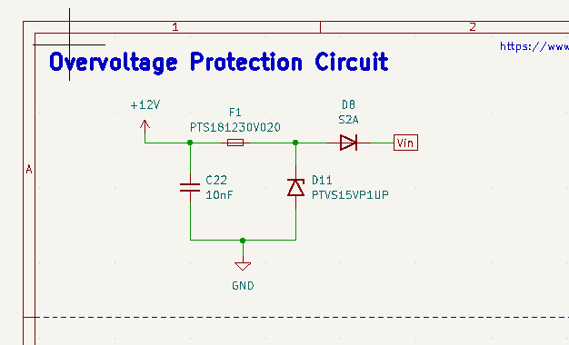
After this, I started researching STN2100 (STN2100 is a 28-pin OBD to UART interpreter IC that provides bi-directional, half-duplex communication with all vehicle OBD-II legislated protocols) and I would like to include this in my board. In this research, I came around the section Overvoltage Protection Circuit, and decided to include Overvoltage and reverse polarity protection for my power circuit in order to protect my car (in which I plan to test this) and my newly designed board.
The circuit is pretty simple as shown in the image below.
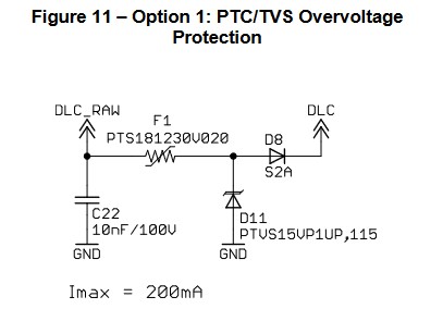
And after I translated that into KiCad I have something like this.
Final words
In order to power ESP32 from the OBD port I will use only the circuits described in the sections above. One is for protection of overvoltage and reverses polarity and the other one is to step-down voltage from 12V to 3.3V. In the next post, I will add to this schematic and design in order to add OBD to the UART interpreter and to add the CAN transceiver as well. Also, I will need to connect everything to ESP32-S3, but on that topic, more in a future post. Do you have any questions or suggestions about my implementation? please comment down below and see you at the next one.