

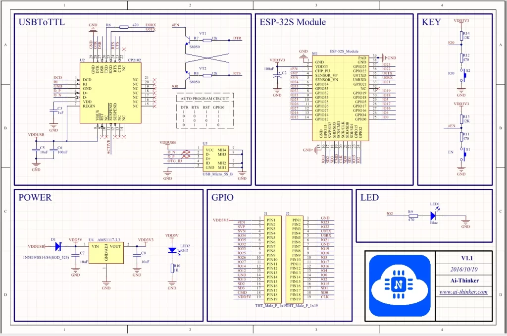
Hi All. In this post, I want to cover everything that is in one ESP32 dev board. Everything that is needed, that is nice to have and/or we can do without. For this ESP32 board review, I will review the board that I have and that is NodeMCU-32S from Ai-Thinker. This is one of the first ESP32 dev boards and now it’s pretty outdated, but it’s still good as an example of all the necessary components that are needed in order to have a working esp32 dev board. So let us begin.

But first, we need to know what is difference between ESP32 and ESP32 development board? ESP32 is actually a series of low-cost system-on-chip Microcontrollers that have integrated WiFi and usually Bluetooth connection. In order to use ESP32, we need somehow to power this system on a chip, program, and communicate. Because of this, we have a development board that is making the development of programs and applications much easier, because now we have the bare minimum that is needed in one board that we can simply plug in our PC and start developing. So, let us think of development boards as a minimum of extra components that are needed for basic work with ESP32.


Check out my custom ESP32 development board that I’m designing in KiCad in the next link https://blnlabs.com/how-to-add-usb-type-c-to-esp32-development-board/
And as I already did we can split the needed components into the next sections:
- Powering esp32
- programming/communication
- MISC
Powering ESP32
As we want to start developing programs for esp32 as soon as possible we are probably powering our esp32 for our PC, more precisely, from the USB port. With a USB port, we have enough power and communication. But here is the first problem. USB has 5V power and we need 3.3V for ESP32 in order to work. For this we are using linear voltage regulator to drop down voltage for 5V to 3.3V.

In the image above we can see the implementation in NodeMCU-32S. Simply implementation based around ams1117 fixed voltage regulator to 3.3V. Besides that, we have input and output capacitors C7 and C8 and we have one Schottky diode for reverse voltage protection on the input. Also, on the 5V input side, we have one red LED diode with a current limiting resistor of 1K.
Programming/Communication
In order to talk with ESP32, we need a USB to UART chip (USBtoTTL) to translate data from USB into something that ESP32 can understand. If we are using CP2102 and from Datasheet we have a definition
The CP2102 USB to UART Bridge provides a complete plug and play interface solution that includes royalty-free drivers. This USB 2.0 compliant device includes 0 digital I/O pins and is available in a 5×5 mm QFN28 package.
Silabs CP2102 DataSheet
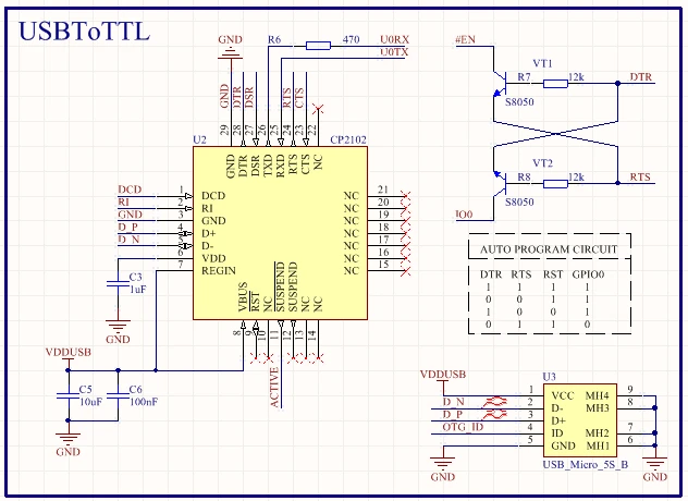
And if we check the image above we can see that we have a USB Micro B connector that is then connecting to CP2102. We are interested in D_P and D_N, which are positive and negative data lines of USB. CP2102 should provide us with U0RX and U0TX, which are UART lines that go directly to ESP32. In the image above we have a section that is for UART flow control and focused on DTR (Data Terminal Ready) and RTS (Request To Send) pins. With these two pins, we can put our ESP32 into boot mode and/or reboot it via UART communication. This is useful when programming and downloading code. We have here a simple circuit that is mapping these two signals to Enable signal and IO0 (boot pin) with the function diagram shown in the image below.

In order to determine the boot mode, we need to take care of GPIO0 and Enable pin. If GPIO0 is pulled up we have SPI (internal) boot and if GPIO0 is pulled down we can download code to our ESP32. Also, we have Enable pin (CHIP_PU) which needs to be pulled up in order for ESP32 to be powered or pulled down in order to reset ESP32. Because of this, we have to Pull up the resistor on both pins, with push buttons on the ground side in order to go to download mode or reboot devices. The circuit for this is shown in the image below.

MISC
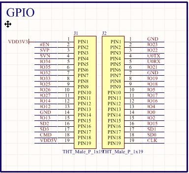
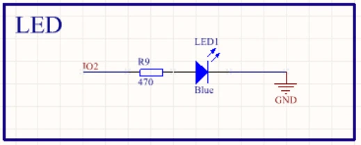
In the MISC section, we have two simple things. We have a simple programmable led diode and simply break out the header. A programmable diode is connected to one GPIO pin and has only a current limiter resistor in series.
Final words
And this is pretty much all for this ESP32 board review. When we break down NodeMCU we can see that it is only necessary components that we can put into only three categories. Besides powering and communication/programming we don’t have much else, but exactly this is the reason why NodeMCU is a good development board. It can be low-cost and easy to use, and you can always extend functionality by adding additional hardware to some of the breakout pins. What do you think about ESP32? is it maybe to bear-bone? If you want to start with ESP32 check out my YouTube video
See you in the next one.