
Hi all. ln this post I would like to go a bit in detail about what is actually ws2812b. How does this work for us in order to create full addressable RGB clock? Check this first part for RGB Led Wifi Clock at the next link.
So lets begin.
Datasheets
There are a couple of datasheets online regarding ws2812b Led IC but they look like they are 20 years old. Please look at one of the datasheets for WS8212b at next link https://cdn-shop.adafruit.com/datasheets/WS2812B.pdf. Because of that, I decided to create my own graphs to represent the functionality of ws2812b.
Logical Levels
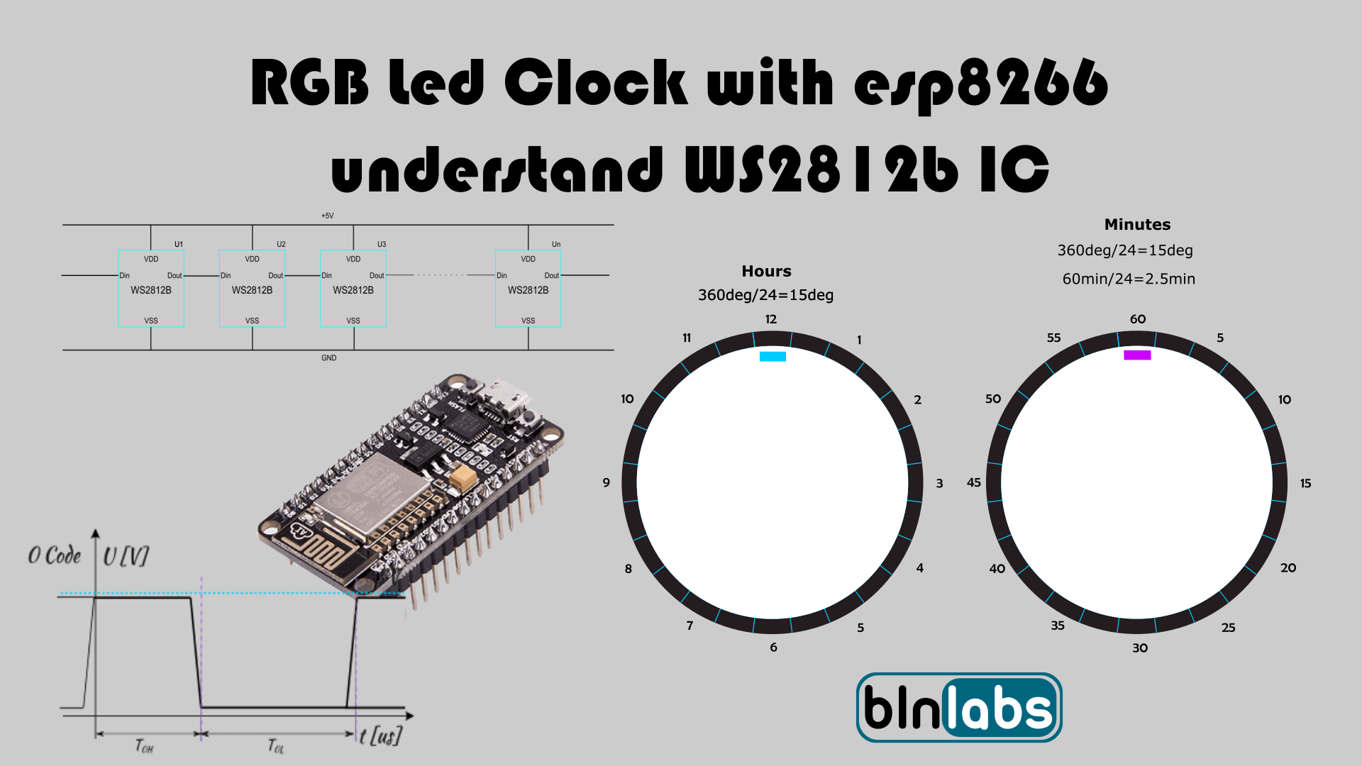
To control anything first we need to know how to represent two levels, logical zero and logical one. In this IC that is done with PWM. So, with changing duty cycle we are changing do we want to send a logical zero or a logical one. For Logical zero duty cycle is around 32%. For logical one around 64% which is shown on the image below. The other signal that we need to know is a defined reset signal. The reset signal will define the end of communication and in this IC that is RET code and it’s also defined in the image below.

Connection
When we have an understanding for we can send logical 0 of 1 and signal the end of the communication cycle we need to know how to connect multiple led ICs. For ws2812b we just need to connect ICs in a cascade way. This means that data will travel to the first IC and pass-thru and then arrive at the second IC and so on.

So, we have this cascade line and now we need to send data to all IC at the current data cycle. We can do this by creating the message for N IC where 24bit represents data for one IC and if we have 4 ICs we need to create a data signal 4*24bits long. One more thing. If we look at the time axis, we can see that the first data that we need to generate is the 24bit date for the farthest IC in the chain. In the image below we can see the signal definition for N ICs connected in cascade.

IC Control
But what does that 24bit for a single IC represent? You can take a guess and it’s pretty clear if we remember that we want to control RGB LED. So, we have data for control for Red, Green, and Blue parts for our led and for every color that is defined as 8 bits. Just one thing, if you look at the image below, just notice that the first color defined is green. This is a bit strange because in most cases the first color defined is red, and you will have to swap values for green and red in order to get the desired color.

Final words
With this knowledge, we have enough information to create logic that will transform time data (we receive from NTC clock) and to create the corresponding signal to achieve the functionality of RGB led clock that is described in part one of these series. Please comment down below if you have any questions about ws2812b. In the next post, I will try to combine everything in the working prototype for RGB Led Wifi Clock. Check out my other project at https://bln364.com/ and see you in the next post.
Nice project and writeup. My suggestion is to use I2S hardware module of esp8266 to control the ws2812b