
First prototype
Hi all. At the end of this post, we will have a working first prototype of LED WiFi clock using esp8266. So, in the first two parts of this project led clock series we installed IDE, and learned who to set up the Wifi manager. In this post we will cover the last two logical parts of this project:
- NTP Client
- Control WS2812B Module Strip 24 Bits 24
In the end, we will connect our esp8266 dev board to WS2812B Module Strip 24 Bits 24 and put all parts together in order to get full functionality.
NTP Client
First, what is NTP?
The Network Time Protocol (NTP) is a networking protocol for clock synchronization between computer systems over packet-switched, variable-latency data networks. In operation since before 1985, NTP is one of the oldest Internet protocols in current use. NTP was designed by David L. Mills of the University of Delaware.
Wikipedia
With NTP client and internet connection we can get current time based on our time zone and we don’t ever have to configure our clock. And now, as for Wifi manager, I wanted to test this functionality stand alone in order to understand it, so I wound some example and modified it a bit.
We need an internet connection in order to access to NTP server, so in the start-up phase, I would like to connect to the net.
const char *ssid = <your wifi hotspot name>;
const char *pw   = <your wifi hotspot password>;
....
void setup() {

  Serial.begin(115200);

  Serial.println("Connecting to WiFi...");
  WiFiMulti.addAP(ssid, pw);
  while (WiFiMulti.run() != WL_CONNECTED) {
    delay(1000);
    Serial.print(".");
  }
  Serial.println("\nConnected.");

}
Next, we need to configure the NTP client. To configure to which server we will talk to, how recent, our timezone. And that is done with the next set of commands:
const long timezoneOffset = 2 * 60 * 60; // ? hours * 60 * 60

const char          *ntpServer  = "pool.ntp.org"; // change it to local NTP server if needed
const unsigned long updateDelay = 30*60*1000; //900000;         // update time every 15 min
const unsigned long retryDelay  = 5000;           // retry 5 sec later if time query failed
const String        weekDays[7] = {"Mon", "Tue", "Wed", "Thu", "Fri", "Sat", "Sun"};
And we need to add next to commands to init phase if we have connection to internet
  timeClient.setTimeOffset(timezoneOffset);
  timeClient.begin();
Our main job in done, now we just need simply to periodically call function timeClient.update() in order to get current time and then extract that value with command timeClient.getHours(), timeClient.getMinutes() and timeClient.getSeconds().
Please check out the complete example that I tried on my side.
#include <ESP8266WiFi.h>
#include <ESP8266WiFiMulti.h>
#include <NTPClient.h>
#include <WiFiUdp.h>

const char *ssid = <your wifi hotspot name>;
const char *pw   = <your wifi hotspot password>;
const long timezoneOffset = 2 * 60 * 60; // ? hours * 60 * 60

const char          *ntpServer  = "pool.ntp.org"; // change it to local NTP server if needed
const unsigned long updateDelay = 30*60*1000; //900000;         // update time every 15 min
const unsigned long retryDelay  = 5000;           // retry 5 sec later if time query failed
const String        weekDays[7] = {"Mon", "Tue", "Wed", "Thu", "Fri", "Sat", "Sun"};

unsigned long lastUpdatedTime = updateDelay * -1;
unsigned int  second_prev = 0;
bool          colon_switch = false;

ESP8266WiFiMulti WiFiMulti;
WiFiUDP ntpUDP;
NTPClient timeClient(ntpUDP, ntpServer);

//https://github.com/olikraus/u8g2/wiki/u8x8reference

void setup() {

  Serial.begin(115200);

  Serial.println("Connecting to WiFi...");
  WiFiMulti.addAP(ssid, pw);
  while (WiFiMulti.run() != WL_CONNECTED) {
    delay(1000);
    Serial.print(".");
  }
  Serial.println("\nConnected.");

  timeClient.setTimeOffset(timezoneOffset);
  timeClient.begin();

}

void loop() {

  if (WiFiMulti.run() == WL_CONNECTED && millis() - lastUpdatedTime >= updateDelay) {
    bool updated = timeClient.update();
    if (updated) {
      Serial.println("NTP time updated.");
      lastUpdatedTime = millis();
    } else {
      Serial.println("Failed to update time. Waiting for retry...");
      lastUpdatedTime = millis() - updateDelay + retryDelay;
    }
  } else {
    Serial.println("WiFi disconnected!");
  }

  unsigned long t = millis();

  unsigned long epochTime = timeClient.getEpochTimWorking Video e();
  struct tm *ptm = gmtime ((time_t *)&epochTime);
  String year = String(ptm->tm_year + 1900);
  unsigned int month = ptm->tm_mon + 1;
  unsigned int day = ptm->tm_mday;
  unsigned int hour = timeClient.getHours();
  unsigned int minute = timeClient.getMinutes();
  unsigned int second = timeClient.getSeconds();
  String weekDay = weekDays[timeClient.getDay()];

  if (second != second_prev) colon_switch = !colon_switch;

  String fDate = (month < 10 ? "0" : "") + String(month) + "/" + (day < 10 ? "0" : "") + String(day);
  String fTime = (hour < 10 ? "0" : "") + String(hour) + (colon_switch ? ":" : " ") + (minute < 10 ? "0" : "") + String(minute);

  //Serial.println(fDate);
  Serial.println(fTime);

  second_prev = second;

  int diff = millis() - t;
  delay(diff >= 0 ? (500 - (millis() - t)) : 0);

}
For the example above we are getting current time on our serial monitor periodically. The next thing for us is to learn how we can control our 24 bit RGB LED circle.
Connect LED circle to esp8266 dev board
Let’s connect our LED circle in order to test it. In this case, this required a bit of soldering, because we didn’t have pins on our WS2812B Module Strip 24 Bits 24, just pads directly on PCB.
I will not explain in detail how to solder in this post, but my procedure was something like this. First, just add a bit of solder on each pad. In the images below you can see LED circle before and after this step.

before 
after
Then connect the different color wires to pads. I used red wire for Vcc, black for ground, yellow for data in, and gray for data out.
The final product is shown in the image below.

And now we can connect it to our esp8266 dev board. For this example, I will use power directly from the development board. Yes, it’s 3.3V and the requirement for WS2812b said that the operation range is from 3.3V to 5.5V. So, we are at the edge on operation voltage here. This is not good enough for the final product but for prototype, it’s good enough. So, let’s connect:
- 3.3V of esp8266 dev board to VCC pin for our LED circle.
- G (ground) of esp8266 dev board to GND pin for our LED circle.
- D5 (Data pin) of esp8266 dev board to Data in (IN) pin for our LED circle.
- leave Data out (OUT) pin of LED circle unconnected
Fast LED
In order to control WS2812b and all 24 of our led diodes, we need a library called FastLED. This library is very simple to use so I will show you the first example that I ran, and then go over line by line.
#include <FastLED.h>

// #define CONTROL_PIN 7 // Arduino pin
#define CONTROL_PIN D5 // esp8266

#define LED_COUNT 24

CRGB ring_leds[LED_COUNT];
int index = 0;

void setup() {
  // put your setup code here, to run once:
  FastLED.addLeds<WS2812B, CONTROL_PIN, GRB>(ring_leds, LED_COUNT);
  Serial.begin(115200);

}

void loop() {
  // put your main code here, to run repeatedly:

  memset(ring_leds, CRGB(0,0,0), sizeof(ring_leds));
  ring_leds[5]= CRGB(0,0,10);
  ring_leds[10]= CRGB(10,0,0);
  ring_leds[index]= CRGB(0,10,0);
  index++;
  if(index>23)index=0;
  FastLED.show();
  delay(1000);

}
We need to define the number of LEDs in our system (#define LED_COUNT 24) and data out pin from our esp8266 dev board (define CONTROL_PIN D5 // esp8266).
Next, we need to set up FastLED driver to our desired chip, in our case WS2812b with command.
FastLED.addLeds<WS2812B, CONTROL_PIN, GRB>(ring_leds, LED_COUNT);
And now I just need to set the right element in array ring_leds to correspond with real led on our LED circle. For the first led, we need to set ring_leds[0], and for the last led, we need to set ring_leds[23]. When we are pleased with the configuration that is now inside the ring_leds array, we need to call function FastLED.show(), which will create a data signal for ring_leds array (that we talked about in part 2), and that will set the desired color to our led circle.
Put all together
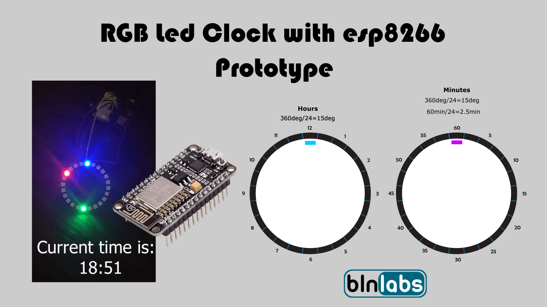
We have everything working separately now we just need to add everything in one Arduino Sketch. First, add WiFi manager, and then with NTP Client get current time data. Next, implement a function that will translate current time into index number for ring_leds array for hours, minutes, and seconds in logic that we defined in part 1 of this project Led Clock.
My translation functions look like this:
int Cal_HoursLed(NTPClient* timeClient){
  unsigned int hour = timeClient->getHours();
  unsigned int led_index = 0;
  Serial.println(hour);

  if (12<=hour){ // PM
    hour-=12;
  }
  else{  // AM
    // do nothing
  }

  led_index = hour*2;
  Serial.println(led_index);
  return led_index;
}

/** @brief Translated Minutes value into position in LED array
 *
 *  @param timeClient NTP Client object containing current time
 *  @return index.
 *
 */
int Cal_MinsLed(NTPClient* timeClient){
  unsigned int mins = timeClient->getMinutes();
  unsigned int led_index = 0;
  led_index = (float)mins/2.5;
  Serial.println("mins debug");
  Serial.println(mins);
  Serial.println(led_index);
  return led_index;
}

/** @brief Translated seconds value into position in LED array
 *
 *  @param timeClient NTP Client object containing current time
 *  @return index.
 *
 */
int Cal_SecsLed(NTPClient* timeClient){
  unsigned int secs = timeClient->getSeconds();
  unsigned int led_index = 0;
  led_index = (float)secs/2.5;
  Serial.println("Sec debug");
  Serial.println(secs);
  Serial.println(led_index);
  return led_index;
}
And then we can call function about in the main loop.
      // Set coresponding leds
      ring_leds[Cal_HoursLed(&timeClient)] = ring_hours_led;
      ring_leds[Cal_MinsLed(&timeClient)] = ring_mins_led;
      ring_leds[Cal_SecsLed(&timeClient)] = ring_secs_led;

      FastLED.show();
      delay(1000);
By switching the order of execution we can set the dominant indicator. In the way shown above dominant indicator is seconds indicator led. This means that if all three indicators want to activate a single led diode, the color that is defined for seconds indicator will be set last, so it will proceed to FastLED.show() and the to device itself.
Testing
In the video above you can see that everything is working at the first sight. But, if we that a closer look we can notice a short blinking of led with index 0. This is because we are working on the edge of the operation voltage of the WS2812b chip. When I created a blinking sequence for Arduino Uno this blinking stopped (Arduino Uno has 5V logic and esp8266 has 3,3V logic). So, in the next post, we will fix this issue.
Final words
This is a very interesting project for me, and maybe I would like to create a product out of this. That means to create custom PCB (PCB will hold esp8266 or esp32, led diodes WS2812b …), add configuration inside WiFi manager for time zone and maybe NTP server, and so on. Will this be interesting for you? Please comment down below and see you in the next post.